Acoustical tube

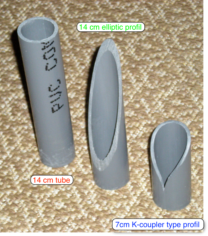
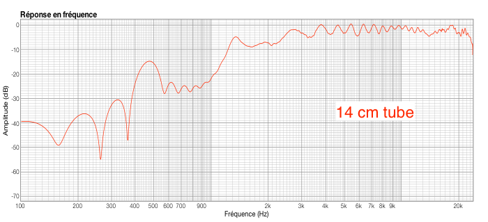
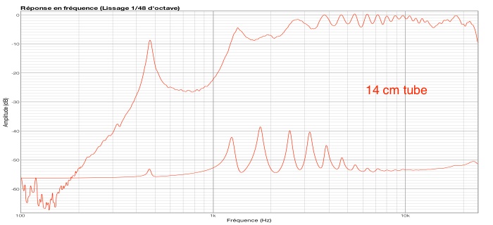
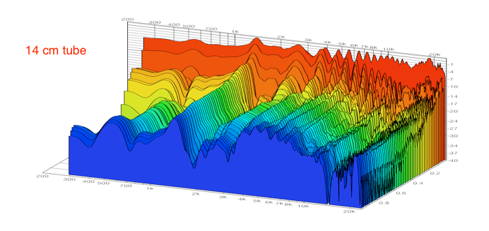
Tube 14 cm long
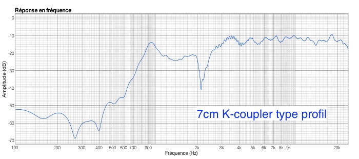
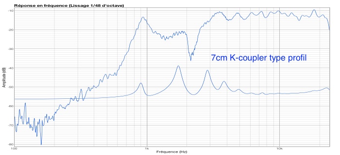
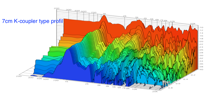
Profile-type "K-coupler" about 7cm
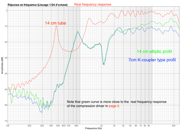
Direct comparison


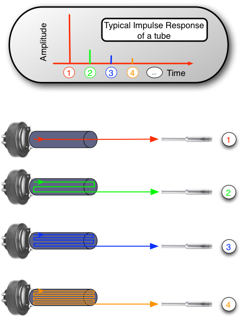
Schematic explanation of sound propagation in a tube:


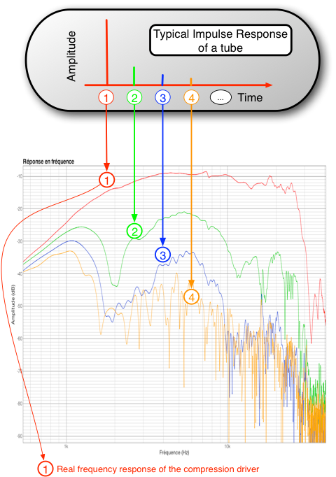
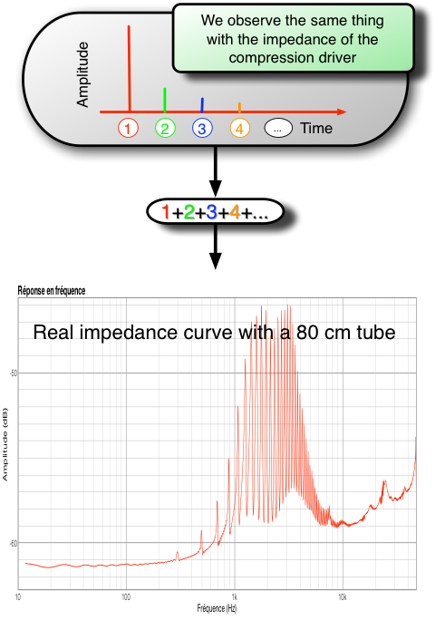
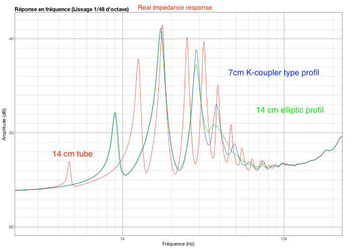
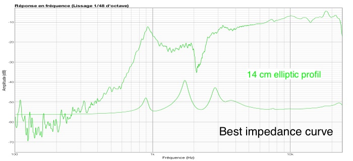
This comb filter on the impedance curve of the compression driver is also for exactly the same reason as for the amplitude curve as shown in the picture below:
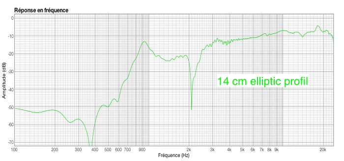
Comment curves impedance: The impedance curves show clearly that the elliptic shape reflected less.
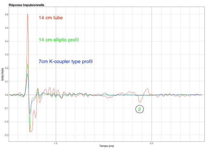
This shows that the most significant is the first echo, denoted 2.
Presentation:
On this page is studying the role of the mouth of a tube on the propagation of sound from a compression chamber to the other end of this tube.
The amplitude curve of each of its fragments of energy that arrives at a regular interval according to the length of the tube are reflected with their own amplitude curves as seen in the following image:
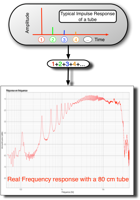
But what will really be heard is the sum of the main signal and its echoes, the respective time delays resulting in interference, which give a comb filter, as shown in the picture below:
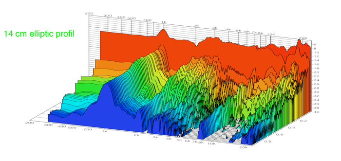
Comment: The 14cm tube measures show a similar result to the measurement of the 80cm tube, ie the appearance of comb filter.
Comment: The answer is not good below 3000Hz, we can not really talk amplitude response comb response but undulating.
The curve shows the impedance behavior of the same gender as undulating.
Comment amplitude curves: There are differences in noise level, however the microphone and the signal level measurement are unchanged.
This is because the mouth of the single tube is very close to the microphone, while the elliptical profiles and K-type cutter (which are shorter) releases the acoustic energy away from the microphone
When the sound coming out of the speakers came to the other end of the tube, part of the sound energy is sent back inside the tube.
This energy will reach the compression and another part is returned to the mouth of the tube, this cycle is repeated a number of times as illustrated by the following image:
Cutting bevel of about 14 cm long

Comment: If the answer is not good below 3 kHz and with the K-coupler comb filter is however virtually eliminated.
The impedance curve shows very well, there was little fluctuation thereof.
Measurement of three different types of outlets:
We will now measured amplitude curve with 3 differents mouths, namely:
-
1.1) 14 cm Single tube
-
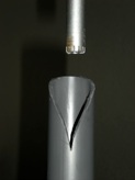
2.2) Elliptical shape over a length of about 14cm
-
3.3) K-coupler over a length of about 7cm
The measuring conditions are the same each time. Only the types of tube are inter-changed.
The microphone is positioned approximately 25cm from the acoustic origin.
Compression driver: BMS 4540ND
Original file: Acousticaltube.pdf